MISC study notes about ARM AArch64 Assembly and the ARM Trusted Execution Environment (TEE)

Disclaimer: These are unfiltered study notes mostly for myself. Guaranteed not to be error free. So if you did land here, managed to get to the end of it and found some mistakes just hit me up, I'd love to know what's wrong :)
AArch64 - Preface
Basic assembly terminology for the sake of completeness:
label1:                     ; this is a label
  .word variable1           ; this is the directive .word, defining a variable
  add R1, #1                ; this is a assembly instruction
Next let's setup a test environment for whats coming next. In particular I want to run a recent RaspbianOS in QEMU. If you have a spare RaspPi or any other ARM AArch64 devboard with some Linux lying around you can skip this step.
pwn@host$ mkdir aarch64_tests && cd aarch64_tests
pwn@host$ wget https://downloads.raspberrypi.org/raspios_arm64/images/raspios_arm64-2022-01-28/2022-01-28-raspios-bullseye-arm64.zip | busybox unzip -
pwn@host$ sudo mkdir /mnt/raspbian
pwn@host$ fdisk -l 2022-01-28-raspios-bullseye-arm64.img
# Check the 'Start' value of 2022-01-28-raspios-bullseye-arm64.img1 and multiply by 512 That will be your **N**
pwn@host$ sudo mount -v -o offset=N -t vfat 2022-01-28-raspios-bullseye-arm64.img /mnt/raspbian
pwn@host$ cp /mnt/raspbian/kernel8.img $(pwd)
pwn@host$ cp /mnt/raspbian/bcm2710-rpi-3-b-plus.dtb $(pwd)
pwn@host$ sudo umount /mnt/raspbian
# Ensure you have QEMU 6.0 installed at this point
pwn@host$ qemu-img resize 2022-01-28-raspios-bullseye-arm64.img 8G
pwn@host$ qemu-system-aarch64 -m 1024 -M raspi3 -kernel kernel8.img -dtb bcm2710-rpi-3-b-plus.dtb -sd 2022-01-28-raspios-bullseye-arm64.img -append "console=ttyAMA0 root=/dev/mmcblk0p2 rw rootwait rootfstype=ext4" -nographic -device usb-net,netdev=net0 -netdev user,id=net0,hostfwd=tcp::5555-:22
# At this point raspbian should boot on the terminal
raspberrypi login: pi
Password: raspberry
pi@raspberry:~$ sudo service ssh start
pi@raspberry:~$ sudo update-rc.d ssh enable
# At this point we should have been inside the QEMU RaspbianOS instance with ssh
pwn@host$ ssh pi@127.0.0.1 -p 5555
pi@raspberry:~$ sudo apt update && sudo apt install neovim nasm -y && bash -c "$(curl -fsSL http://gef.blah.cat/sh)"
Note: I noticed when switching to my MBP that the above doesn't fully work on macOS (missing network within QEMU). No idea for a workaround yet, so if you have one LMK please :)! As a workaround, I've been using cross-compiling on the go by setting up a Ubuntu VM and installing gcc-aarch64-linux-gnu. With that out of the way, let's dive right in.
ARM Basics (especially AArch64)
- ARM since version 3 are BI-endian!
- AArch64 instruction width is 32-bit and little-endian
- AArch64 SCTLR_EL1.E0E (system control register, bit 25), which is configurable at EL-1 or higher determines the data endianess for execution at EL-0/EL-1!
- Ref
- There are separate control registers for each EL, among other configuration registers
- ARMv7 (32-bit): Similarly to the endianess switch capabilities a status register (CPSR) is responsible for indicating thumb mode (see note below)
- Thumb v1 - 16 bit instructions -> ARMv6 and earlier
- Thumb v2 - 16-/32-bit instructions, extends Thumb v1 with more instructions -> ARMv6T2, ARMv7
- ThumbEE - Includes some changes and additions aimed for dynamically generated code
- Differences between ARM and Thumb:
- Conditional execution: Whereas all instructions in ARM support it, only some ARM processores allow conditional execution in thumb mode
- When we talk 32-bit instruction width, the thumb ones typically have a .w suffix
- Barrel shifter is ARM exclusive (e.g.:
mov r1, r0, LSL #1which is equal to r1 = r0 * 2)
- When and how does the processor switch states:
- When using BX (branch and exchange) or BLX (branch, link, and exchange) and setting the destination reigster's LSB to 1
- If the corresponding CPSR bit is set
- NOTE: AArch64 only supports one instruction set, namely A64, so no thumb mode!
- NOTE: Multitude of different ARM architectures that can bring specific nuances to the table
- ARM instruction encoding: MNEMONIC{S} {condition} {dest_register}, op1, op2
- Register names are not prefixed:
- e.g.:
add r0, r1, r2 // load r0=r1+r2
- e.g.:
- Immediate values are not prefixed with a character:
- That said that may be prefixed with a #
- e.g.
add r0, r1, 99oradd r0, r1, #99
- Indirect memory access is indicated by square bracket []
- Destinations are given as the first argument!
LDR(Load)/STR(Store) instruction can be suffixed with:- Q = qword = 64 bits
- D = dword = 32 bits
- W = word = 16 bits
- B = byte = 8 bits
- Registers
- r0 - r30 - general naming scheme
- x0 - x30 - for 64-bit wide access (same registers as r0 to r30)
- w0 - w30 - for 32-bit wide access (same register, upper 32-bit are either cleared on load, or sign-extended
- Register '31' is dual purpose:
- For instructions dealing with the stack, it's the stack pointer rsp
- For all other instructions, it's a "zero" register, which returns 0 when read and discards data when written, named rzr (xzr, wzr)
- There are also SIMD/FP/Vector registers v0 - v31
- Sys-/Function-call behavior:
- r0 - r7 For argument and return values; additional arguments are on the stack
- For syscalls: The syscall number is in r8
- Note: When we deal with SMC calls to switch ELs the
SMC_IDis provided in registerx0!
- Note: When we deal with SMC calls to switch ELs the
- r9 - r15: For temporary values (no guarantee that these are saved for later access)
- r16 - r18: For intra-procedure-call and platform values (avoid when manually writing assembly)
- r19 - r28: Called routine is expected to preserver these and they're safe to use when writing assembly
- r29 / r30:: Used for the frame register and link register respectively (avoid)
- Note: Loading arbitrary immediates
- Loading immediates in non AArch64 is a tad limited and different than how you'd do it on x86
- Recall: All instructions are 32-bit wide
- Only a subset (namely 8-bits) can be used for addressing imms (which is equal to u8::MAX aka 255)
- To form arbitrary values we need to use
rorthat allows values between 2 to 30 or useldr <reg>, =<imm>to load an appropriately sized arbitrary immediate from the literal pool - So how does this translate to AArch64:
- Any value larger than 0xffff cannot be moved in a single
movinstruction either!
- Any value larger than 0xffff cannot be moved in a single
- Some key differences to A32:
- AArch64 has no
LDM,STM,PUSH, orPOPinstructions anymore!- We now have to use
LDPandSTPfor these! - Similarly there seems to be no proper replacement for
LDMIA,STMIA,LDMIB,STMIB,LDMDA,LDMDB,STMDA, andSTDMDB(Ref)- Suffixes: -IA (increase after), -IB (increase before), -DA (decrease after), -DB (decrease before)
- Sidenote: On A32
PUSHis really just a synonym forSTMDB sp!andPOPtranslates toLDMIA sp!
- We now have to use
- Unaligned memory access is now supported by almost all instructions (nice)
- In A64 the stack pointer has to be 128-bit (16 byte) aligned (half that in A32)
- NO conditional execution in A64 (with the exception of branch-, select-, and compare-instructions)
- A32 supports condition codes, e.g.:
addeq, r0, r1, r2 // only executes if the ZERO flag in the CSPR is set - Thumb mode has the
itinstructions:it- if-then (next instruction is conditional)itt- if-then-then (next 2 instructions are conditional)ite- if-then-else (next 2 instructions are conditional)itte- if-then-then-else (next 3 instructions are conditional)ittee- if-then-then-else-else (next 4 instructions are conditional)- Each
itstyle instruction is followed by a condition code - All following 1-4 instructions need to include either the same or inverse condition code
- A32 supports condition codes, e.g.:
- AArch64 has no
Condition flags
| Flag | Description |
|---|---|
| N | Set if a result of an operation is negative, cleared otherwise. |
| Z | Set if a result of an operation is zero/equal, cleared otherwise. |
| C | Set if an operation results in a carry/overflow, cleared if no carry. |
| V | Set if an operation results in an overflow, cleared if no overflow. |
Condition codes
Recall these codes where widely used in A32, whereas in A64 conditional execution has been mostly removed with the exception of branching, select, and compare instructions!
| Mnemonic | Description | Condition flag |
|---|---|---|
| EQ | Equal | Z set |
| NE | Not Equal | Z clear |
| CS/HS | Carry Set | C set |
| CC/LO | Carry Clear | C clear |
| MI | Minus | N set |
| PL | Plus/Positive/Zero | N clear |
| VS | Overflow | V vet |
| VC | No Overflow | V clear |
| HI | Unsigned Higher than or equal | C set && Z clear |
| LS | Unsigned Less than or equal | C clear && Z set |
| GE | Signed Greater than or equal | N == V |
| LT | Signed Less than | N != V |
| GT | Signed Greater than | Z clear && N == V |
| LE | Signed Less than or equal | Z set && N != V |
| AL | Always. Normally omitted | Any |
ARMv8 Privilege levels (aka Exception Levels)
- EL-0 (Application privilege level) - Supported by CPU architecture
- EL-1 (Kernel privilege level) - Supported by CPU architecture
- EL-2 (Virtualization privilege level [Optional]) - Supported by CPU architecture
- EL-3 (Secure privilege level) - Supported by CPU architecture or a dedicated embedded security processor
Note: Privilege levels are reversed from e.g. Intel, where Ring 3 in Intel is User mode!
In general, one thing that always holds true, is that code running on e.g.: EL-2 can modify all registers from lower exceptions (least privileged) levels but not vice versa. Each EL has their own version of e.g. system/config registers such as SPSR_EL3, SPSR_EL2, SPSR_EL1, and SPSR_EL0. Depending on the configuration, each EL can use a dedicated stack pointer register, or they can use the EL-0 one! To switch between ELs there's roughly two ways to do so:
- An exception/interrupt is triggered - May trigger a transition from a lower EL to a higher one.
- Returning from an exception/interrupt - Inverse case compared to above.
Which EL handles which type of exception/interrupt is implementation-specific.
ARMv7 Privilege levels
- PL0 - User mode
- PL1 - Supervisor mode
- PL2 - Hypervisor mode
- PL3 - Monitor mode
AArch64 Assembly Basics
Short refresher on how to write basic AArch64 assembly by hand
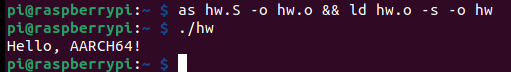
0. Hello World
.data

msg:
        .ascii "Hello, AArch64!\n"
len = . - msg

.text

.globl _start
_start:
        // Prepare write(int fd, const void *buf, size_t count)
        mov x0, #1
        ldr x1, =msg
        ldr x2, =len
        mov w8, #64
        svc #0

        // Prepare exit(int status)
        mov x0, #1337
        mov w8, #93
        svc #0
1. LDR'n'STR
.data
var1: .word 3
var2: .word 4

.text

.globl _start
_start:
        ldr w19, adr_var1    // Load mem addr of var1 via label into w19
        ldr w20, adr_var2    // Same with var2
        ldr w21, [x19]       // Load value located at mem addr x19 as a 32-bit value into w21
        str w21, [x20, #2]   // Store the value from w21 into the mem addr in x20 + 2
        str w21, [x20, #4]!  // pre-indexed: Same as above with a +4 BUT now x20 will be touch and modified: x20 = x20 + #4
        ldr w22, [x20], #4   // post-indexed: Load value located at addr x20 and modify x20 = x20 + #4 as well
        str x21, [x20, x21, LSL#3] // works and means: Store value of x21 in memory x20 with offset x21 << 3
        // Using the extended registers allows to index shift by #3 or #0
        // Using the wide registers allows to index shift by #2
        // This is due to 64-bit variants loading 8 bytes to the dest regiister whereas 32-bit variants only load 4 bytes
        //str w21, [x20, x22, LSL#2]! // pre-index does not allows register offset here
        //ldr x21, [x20], x21, LSL#1  // does not seem to work either

adr_var1: .word var1
adr_var2: .word var2
// INP=addr; as $INP.S -o $INP.o && ld $INP.o -s -o $INP
The whole addressing ordeal boils down to the following:
- Simple:
ldr w0, [x1]->x1is not changed and is equal toint w0 = *x1 - Offset:
ldr w0, [x1, #4]->x1is not changed and is equal toint w0 = x1[1] - Simple:
ldr w0, [x1, #4]!->x1is changed before load and is equal toint w0 = *(++x1) - Simple:
ldr w0, [x1], #4->x1is changed after load and is equal toint w0 = *(x1++)
3. MOV imms Trick
.data

.text

.globl _start
_start:
        mov x0, #256  // valid: since its 1 ror 24
        mov x0, #255  // valid: 255 ror 0
        mov x0, #1337 // invalid on 32-bit ARM
        ldr x0, =1337 // weird limitation bypass
        //mov x0, #0xffffffff // invalid on AArch64 (cannot be loaded in one instruction)
        ldr x0, =0xffffffff   // works like a charm
        mov x0, #0x0000ffff   // u16::MAX is the largest value that can be loaded in a single mov instr on AArch64
The clever label usage here boils down to the following:
- It is allowed to
LDRPCrelative data with a labelldr x0, label // Load value @ label
- Assemblers can support a pseudo Load (immediate) instruction that we have seen above
ldr x0, =imm // Load from literal containing imm
- Ways of obtaining the address of a label:
ldr x0, =label // Load address of label from literal pooladr x0, label // Calculate address of label (PC relative)adr x0, . // Get current PC (address of adr instruction)adrp x0, label // Calculate address of 4KB page containing label
4. {LD/ST}P instead of {LD/ST}M
.data
array:
        .quad 0
        .quad 0
        .quad 0
        .quad 0
        .quad 0

.text

.globl _start
_start:
        adr x0, words+24        // loads address of words[3] in x0
        ldr x1, array_bridge    // loads address of array[0] in x1
        ldr x2, array_bridge+8  // loads address of array[2] in x2
        // ldm r0, {r4, r5} // A32 turns into A64:
        ldp x4, x5, [x0]    // Loads value at x0 in x4 and x0+8 into x5
        // A typical 2 qword stack pop can be written as
        // ldp x0, x1, [sp], #16
        // Pushing on the other hand may look like:
        // stp x0, x1, [sp, #-16]
        stp x4, x5, [x1]  // Counterpart to the above ldp
        // The above instruction in A32 would have been
        // stm r1, {r4, r5}


words:
        .quad 0
        .quad 1
        .quad 2
        .quad 3
        .quad 4
        .quad 5
        .quad 6

array_bridge:
        .quad array
        .quad array+16
5. Detour A-32 IT instruction
Note: This is not valid AArch64 code, it's just here for completeness!
.syntax unified      // This allows us to intermingle A-32 and Thumb assembly here
.text
.globl _start

_start:
    .code 32         // A-32 code
    add r3, pc, #1   // r3 = $pc + 1
    bx r3            // branch + exchange to the address in r3 -> switch to Thumb state because LSB = 1 (is a requirement to enter thumb)

    .code 16         // Thumb mode
    cmp r0, #10
    ite eq           // if r0 is equal 10...
    addeq r1, #2     // ... then r1 += 2
    subne r1, #3     // ... else r1 -= 3
6. Jumps'n'Branches
.data

.text

.globl _start
_start:
        mov w0, #42     // mov 42 into w0
        mov w1, #1337   // mov 1337 into w1
        cmp w0, w1      // w0 - w1 == 0 ? -> NEG flag is set ...
        blt lower       // ... hence we take that jump
        mov w0, w1
        bl end
lower:
        mov w2, w0      // mov 42 into w2
        b end           // uncond branch to label end
end:
        mov w2, #2      // mov 2 into w2
        tbz w2, #2, _start // Test Bit and Branch if Zero -> w2 - #2 == 0?
Worthy to note here is that there exist a few more jump/branch instructions:
* bl - Branch and link to a label while setting x30 to pc+4
* blr - Similar to bl but instead branch to a register
* br - Same as blr but no setting of x30
* cb(n)z - Compare and branch if (non)zero to a label (does a sub, does not discard result, and then sets flags)
* tb(n)z - Test bit and branch if (non)zero to a label (test does a bitwise and, discards result, and sets flags)
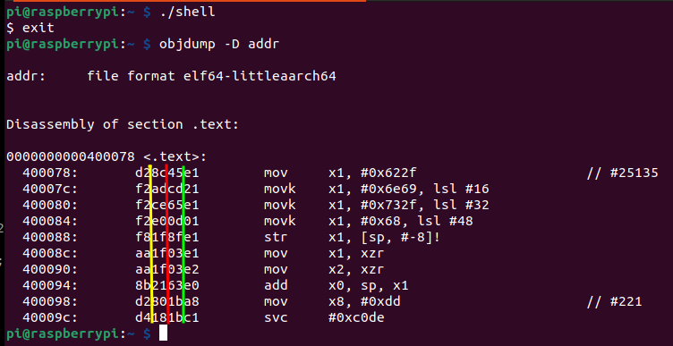
7. AArch64 shellcode
Now for a tad more interesting assembly program, a de-nullified shellcode
.data

.text

.globl _start
_start:
        //execve("/bin/sh", NULL, NULL)
        mov x1, #0x622f                 // "b/"
        movk x1, #0x6e69, lsl #16       // "ni"  ; mov 16 bit immediate with a shift
        movk x1, #0x732f, lsl #32       // "s/"  ; same
        movk x1, #0x68, lsl #48         // "h"   ; same
        str x1, [sp, #-8]!              // sp-8; then store x1 at that new location
        mov x1, xzr                     // zero out x1
        mov x2, xzr                     // zero out x2
        add x0, sp, x1                  // set x0 = sp + x1
        mov x8, #221                    // move execve syscall number in x8
        svc #c0de                       // invoke syscall and provide arbi trary exeception code
TEEs
TEEs are a form of sandbox / isolation environment for critical operations. In general, TEE's seem to provide a level of "assurance" for:
- data confidentiality: Unauthorized entities cannot view data while in use within the TEE
- data integrity: Unauthorized entities cannot add, remove, or alter data while it is in use within the TEE
- code integrity: Unauthorized entities cannot add, remove, or alter code executing in the TEE
This is achieved by splitting the whole environment into a secure or trusted environment and the rest. The secure portion or a proxy layer in the middle then exposes a very limited API with which the normal world can interact to e.g. request operation for a security critical portion.
This separation tries to secure 4 different dimensions:
- Memory
- Execution
- I/O (e.g. UI for secure payment, basically sensors such as the touch sensor)
- Hardware that is shared across boundaries (e.g. crypto engines)
Prominent examples for TEE(-like) implementations are Intel SGX (does not secure 3 & 4), RISV PMP, AMD SEV(-SNP, -ES), ARM's CCA, or Apple's Secure Enclave. The remainder of this blog will only (briefly) discuss ARMs TEE implementation called TrustZone.
The last thing to note is that having a TEE without secure boot (multi-stage bootloader, with each stage verifying the prior one while loading the next) is useless, as the bootloader runs in the highest privileges that could manipulate the boot process. When having e.g. physical access to a device, we could also flash the TEE, which is mostly prevented with the multi-stage approach.
ARM TrustZone
In layman terms, ARM TrustZone can be used to perform hardware-level isolation to keep the TEE secure to avoid a full system compromization. Both the ARM v8-A Profile and the ARM v8-M provide TrustZone Extensions that can be used for SoCs with an integrated V6 or above MMU. Both implementations share similarities but are quite different. Utilizing a TrustZone extension allows for a fully fledged TEE that includes a TEE OS running at S-EL1, trusted drivers (TDs) that securely interact with peripherals, and trusted applications (TAs) that run at S-EL0 (Note the extra 'S' in the exception levels, indicating that there's another layer of exception levels within a TEE with the 'S' meaning secure.).
- S-EL-0: For unprivileged trusted applications, sometimes trusted drivers.
- S-El-1: For the TEE OS and priviliged drivers
- S-EL-2: Non-existent (prior to ARM v8.4).
- S-EL-3: For the secure monitor, running ARM trusted firmware typically provided by a device manufacturer.
Note: To add even more confusion, the sheer amount of different manufacturers that license ARM processors implement their own TEE (usually) based on the official TrustZone extension. Just to name a few that emerged:
- ARM's Trusted Firmware-A TF-A
- The Open-source Portable TEE OP-TEE
- Qualcomm's QTEE
- Samsungs Teegris
- Googles Trusty
- Huaweis iTrustee
Regardless of the different TEE implementations in the wild, three major concepts that all of them use have been observed in the wild:
- Running a fully fledged OS (TEE OS) in secure world (e.g. in Samsung phones, Qualcomm chips)
- Lightweight synchronous library that offers some kind of API (e.g. to load_key()) and has all secret keys stored there (e.g.: in Nintendo Switch)
- A mix between 1. and 2. (rarely seen if ever)
Before jumping into any more specifics, I noticed that when starting to research this whole topic, some different terminology seems to be used for the same thing:
- Normal world aka non-secure world aka untrusted environment aka Rich Execution Environment ("REE")
- Secure World aka Trusted Execution Environment (TEE)
Now with that out of the way, I have to put yet another note here before progressing. This post tries to give a general overview of ARMs TrustZone technology, with a focus on TrustZone-A for Cortex-A chips. As for a general distinction between TrustZone-M and TrustZone-A:
TrustZone in Cortex-A processors use a dedicated mode to handle the switch between the secure and non-secure states. This particular mode is typically referred to as monitor mode. When a processor is in monitor mode, it will always be in a secure state. Further, it will have access to NS bit in the SCR register (1 == non-secure, 0 == secure). This bit in the Secure Configuration Register defines the security state the CPU will switch to after exiting monitor mode. As a result, any switch between secure and non-secure state will go through a single entry point which is the monitor mode.
           +--------+  +--------+  +--------+  +--------+   |   +------------------+
           |        |  |        |  |        |  |        |   |   |                  |
EL-0       |  App   |  |  App   |  |  App   |  |  App   |   |   | Trusted Apps /   |
           |        |  |        |  |        |  |        |   |   | Drivers          |
           +--------+  +--------+  +--------+  +--------+   |   +------------------+
                                                            |
       -----------------------------------------------------+--------------------------
                                                            |
           +--------------------+  +--------------------+   |   +------------------+
           |                    |  |                    |   |   |                  |
EL-1       |  Guest OS          |  |  Guest OS          |   |   |  Trusted OS      |
           |                    |  |                    |   |   |                  |
           +--------------------+  +--------------------+   |   +------------------+
                                                            |
       -----------------------------------------------------+--------------------------
                                                            |
           +--------------------------------------------+   |
           |                                            |   |
EL-2       |  Hypervisor                                |   |      No EL2 here
           |                                            |   |
           +--------------------------------------------+   |
                                                            |
       -----------------------------------------------------+

           +-----------------------------------------------------------------------+
           |                                                                       |
EL-3       |  Secure Monitor                                                       |
           |                                                                       |
           +-----------------------------------------------------------------------+
Based on the diagram above, a typical call-chain with the starting point of an app running on EL-0 and wanting the TEE to work on a specific task would start with triggering an exception for the guest os (normal system kernel) to handle by using the svc instruction ("supervisor call"). The kernel then depending on the requested operation notifies either the hypervisor with the hvc instruction ("hypervisor call") or by using the smc instruction ("secure monitor call") directly moving execution into the secure monitor on EL-3. The secure monitor then calls the requested functionality in the secure world, which then in turn either has to use svcor smc (depending on where execution is happening) to redirect execution back to the secure monitor to return the computed results.
A short note on the trusted applications (TAs) in the secure world: These can be anything ranging from DRM, a trusted UI, a crypto manager, fingerprint storage or storage of other secrets and keys in general. Such TAs are fully scheduled / maintained / loaded from the TEE OS. While the above is the typical flow of execution when switching between NS and S states, the communication between the two worlds can take different forms:
- With an SMC as described above, returning a computed result via a register back to the normal world
- The operation in the secure world writes the result into some shared memory to which both the NS-world and S-world have access to. After completion of the requested operation, the call-chain from NS⇾S is then reversed, with the secure world notifying the non-secure world that the results are available.
- Some specific (hardware) related functionalities a non-secure world app may need access to in e.g. edge cases (create a watchdog timer for rebooting on hang) or accessing other SoC components on the board may be directly exposed by a TEE purposely to be accessible from EL-1 (of the non-secure world). Alternatively, a direct communication channel between EL-0 apps and S-EL-0 trusted apps is possible as well (bypassing the long call chain from EL-0 to S-EL-0).
Back to secure memory: The CPU can also mark whole pages of memory as either belonging to the secure world or belonging to the normal world to make memory read/writes more restrictive. The NS bit of a Page Table Entry (PTE) determines whether the page belongs to either of the two worlds. This bit also controls whether the AxPROT[1] bit is set when accessing a device's DRAM (This is on the MMU level!!). On a hardware level (Bus level!) this is implemented with a dedicated controller: The TZASC (TrustZone Access Space Controller). One thing to note here is that the TZASC does not know anything about running software, CPU MMUs, or individual CPU abstractions. It has its own configuration, defining memory ranges and their access rights. Additionally, the same concept exists for SRAM as well, here it's called TZPC (TrustZone Protection Controller). On a very high-level, TZPC aside, this results in the following call chain when the cpu issues a memory read/write request:
              +------------------------+
              |                        |                           +-------------+
              |                        |                           |             |
              |                        |                           |             |
              |                        |    +--------------+       |             |
              |                        |    |  AXI to ABP  |       |             |
              |                        +--->|  Bridge      +------>|             |
              |                        |    +--------------+       |             |        +-------+          +--------+
              |                        |                           |             |        |       |          |        |
              |                        |                           |    TZASC    +------->|  DMC  +--------->|  DRAM  |
+--------+    |                        |                           |             |        |       |          |        |
|        |    |                        +-------------------------->|             |        +-------+          +--------+
|  CPU   +--->|   AXI Infrastructure   |                           |             |
|        |    |                        |                           |             |
+--------+    |                        |                           |             |
              |                        |                           |             |
              |                        |                           |             |
              |                        |                           |             |
              |                        |                           +-------------+
              |                        |
              |                        |
              |                        |
              |                        |
              +------------------------+
The last thing worth noting again for now seems to be that devices that use TrustZone can also use SecureBoot to enforce the integrity of the operating system when it starts booting up from disk to ensures that nobody has tampered with the operating system’s code when the device was powered off. In today's modern hardware, this again is a non-trivial process consisting of multiple stages, with each loading and verifying the integrity of the next. Meaning, it boils down to the following sequence:
- Cold Reset
- Boot Loader stage 1 (BL1) AP Trusted ROM
2.1 Also referred to as a trusted boot ROM SoC TEE config that is usually shipped from a manufacturer. - Boot Loader stage 2 (BL2) Trusted Boot Firmware
3.1 Either from ROM or trusted SRAM - Boot Loader stage 3-1 (BL3-1) EL3 Runtime Firmware
4.1 The trusted OS - Boot Loader stage 3-2 (BL3-2) Secure-EL1 Payload (optional)
- Boot Loader stage 3-3 (BL3-3) Non-trusted Firmware
As for TrustZone in Cortex-M processors, the concept is the same, but the approach is different. We also have two states: secure and non-secure. The major difference being that ARM allows us to implement multiple entry points to switch between states. These entry points are referred to as non-secure callable, which leaves us with 3 states: secure, non-secure and non-secure callable. As for specifics to enter into non-secure callable, there's a dedicated instruction for that: SG (secure gate). Once executed, the CPU will switch to secure state. Switching back to a non-secure state is handled by executing yet another dedicated instruction, either BXNS or BLXNS. Final remark: None of the secure exception levels mentioned above, nor the secure monitor, applies to this processor line! As for some more unsorted points concerning the Cortex-M line of processors:
- In Cortex-M processors we have a flat memory map
- No MMU
- Things are mapped at specific addresses in memory:
- Flash (lowest address) -> RAM -> Peripherals [e.g. Crypto, I2C, Bluetooth, Display, ...] (highest address)
- TrustZone-M allows to partition flash/RAM/peripherals into Secure and non-secure parts
- Secure code can call anywhere into the non-secure world
- To switch from S->NS
BXNS/BLXNSinstructions have to be used! - From NS into S would cause an exception!
- To handle NS->S calls there's a 3rd state: Non-Secure Callable "NSC" in between S and NS.
- An example would be having a NS and S secure kernel running, with the secure kernel exposing certain system calls like load_key()
- The NS kernel would eventually like to call these.
- To do so, the NSC will expose so called "veneer" functions such as load_key_veneer() which make use of an SG (Secure Gateway instruction)
- The SG instruction sets the security level to S and banks registers.
- The SG instruction also sets bit[0] of the LR register to 0, which indicates that the return will cause a transition back from S->NS.
- Ultimately, a veneer function will look like
SG; B.W load_key!
- To switch from S->NS
- To determine what security an address has there's the concept of attribution units
- SAU (Security Attribution Unit)
- Standard across chips, basically defined by ARM how you use this
- IDAU (Implementation Defined Attribution Unit)
- Usually custom for the silicon vendor, can also be identical to SAU
- To get the security of an address, the SAU and IDAU are combined (the most secure of the two determines if its S, NS, NSC)
- SAU (Security Attribution Unit)
- Where is the policy (S, NS, NSC) enforced?
- Implementation-defined mechanisms:
- Secure Advanced High-performance Bus (Secure AHB, S-AHB):
- AHB matrix that carries security attributes with a transition
- Memory Protection Checkers (MPC):
- Filter transitions at AHB peripheral
- Range- or block-based policies for splitting ROM, flash, and RAMs into S/NS segments
- Peripheral Protection Checkers (PPC):
- Filter transitions at AHB peripheral
- Typically single policy for the whole peripheral
- Some implementations allow more fine-grain policies (AHB-APB bridges)
- Secure Advanced High-performance Bus (Secure AHB, S-AHB):
- Implementation-defined mechanisms:
- TrustZone-M vs. TrustZone-A:
- Similarities:
- Hardware isolates secure world (S) from non-secure world (NS)
- Execution modes exist orthogonally
- Key differences:
- Only 2 execution modes (handler ["os kernel"] and thread ["user land"]) instead of EL{0-3}
- No MMU (Memory Management Unit) -> No virtual addressing!
- Optional MPU (Memory Protection Unit) -> Handles memory permissions
- Similarities:
The above-mentioned SAU, can be configured as follows:
- If SAU is off -> the whole flat memory is marked secure
- If SAU is on, but no regions have been configured, still the whole flat memory is marked secure
- To change security of a region there are 5 registers to do this:
- SAU_CTRL - SAU Control register
- SAY_TYPE - Number of supported regions
- SAU_RNR - Region number register
- SAU_RBAR - Region base address
- SAU_RLAR - Region limit address
- Example:
- Selection region 0 - SAU_RNR = 0x0
- Set base addres to 0x1000 - SAU_RBAR = 0x1000
- Set limit address to 0x1fff - SAU_RLAR = 0x1fe0 (why e0 not ff??)
- Enable SAU - SAU_CTRL = 0x1
Study material
Here at the end are a bunch of references you (and I too) should catch up on if this is your cup of tea :)!
- Talks
- Tech Talk 01 | Trusted Execution Environment 101
- 36C3 - TrustZone-M(eh): Breaking ARMv8-M's security
- Breaking Samsung's ARM TrustZone
- Kun Sun. The Security Impact of Caches over ARM TrustZone
- Securing Your Microcontroller with Arm TrustZone Technology | Oren Hollander | hardwear_io Webinar
- Trusted Execution Environments: A Technical Overview of Intel SGX, Arm TrustZone, and RISC-V PMP
- Launching Feedback-Driven Fuzzing On TrustZone TEE - Andrey Akimov
- Laura Abbott, Rick Altherr -Breaking TrustZone M: Privilege Escalation on LPC55S69
- Lists
- Academia
- SoK: Understanding the Prevailing Security Vulnerabilities in TrustZone-assisted TEE Systems [2020]
- Unearthing the TrustedCore: A Critical Review on Huawei’s Trusted Execution Environment [2020]
- RusTEE: Developing Memory-Safe ARM TrustZone Applications [2020]
- Finding 1-Day Vulnerabilities in Trusted Applications using Selective Symbolic Execution [2020]
- PartEmu: Enabling Dynamic Analysis of Real-World TrustZone Software Using Emulation [2020]
- TEE Blogs
- A Deep Dive into Samsung's TrustZone [Quarkslab]
- Trust Issues: Exploiting TrustZone TEEs [Google P0]
- Exploring and Breaking Samsung’s TrustZone: a blog series Parts I-II-III
- TRUSTONIC’S KINIBI TEE IMPLEMENTATION [Azeria Labs]
- TEE Exploitation on Samsung Exynos devices (I/IV) : Introduction [BlueFrostSecurity]
- Breaking TEE Security Part 1: TEEs, TrustZone and TEEGRIS [Riscure]
- The Road to Qualcomm TrustZone Apps Fuzzing [Checkpoint]
- Qualcomm IPQ40xx: Achieving QSEE Code Execution [Raelize]
- KINIBI TEE: TRUSTED APPLICATION EXPLOITATION
- ARM Blogs
- Other